Active vs. Passive PoE Switch: Which Should We Choose?

PoE switch is designed to offer both network connection and power supply to one PoE powered device (PD) through one Ethernet cable. And as the demand for deploying PD devices such as IP phones, IP cameras and access points increases, PoE switch is commonly used in today’s enterprise and campus networks for it helps to reduce deployment complexity and cost. Now we can see there are both active PoE switch and passive PoE switch sold in the market. What exactly are they? Should we use active PoE or passive PoE switches for our network?

What Are Active PoE and Active PoE Switch?

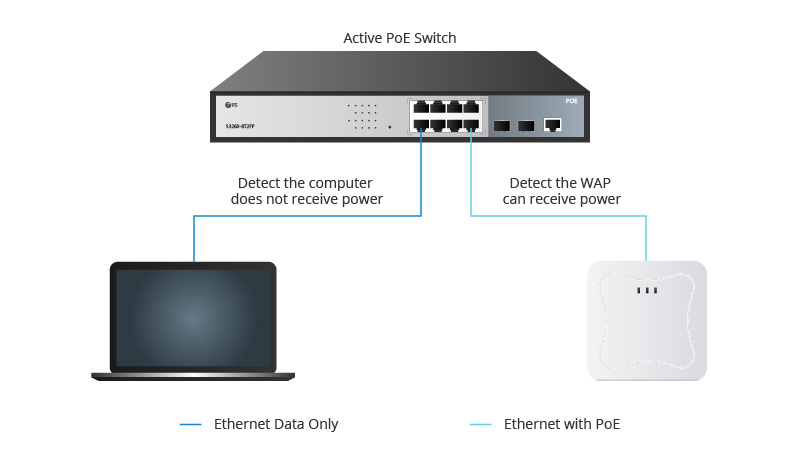
Active PoE, short for active Power over Ethernet, is also known as standard PoE which refers to any type of PoE that negotiates the proper voltage between the power supply equipment (PSE) and the PD device. An active PoE switch is a device that complies with standard PoE, so it is also named a standard PoE switch. This type of switch is rated to be IEEE 802.3af, IEEE 802.3at or IEEE 802.3bt compliant. Thus it can be further divided into PoE, PoE+ and PoE++ switches (PoE vs PoE+ vs PoE++ Switch: How to Choose?). Before powering up, the active PoE switch will test and check to ensure the electrical power is compatible between the switch and the remote device. If it isn’t, the active PoE switch will not deliver power, preventing any potential damage to the non-PoE device.

What Are Passive PoE and Passive PoE Switch?

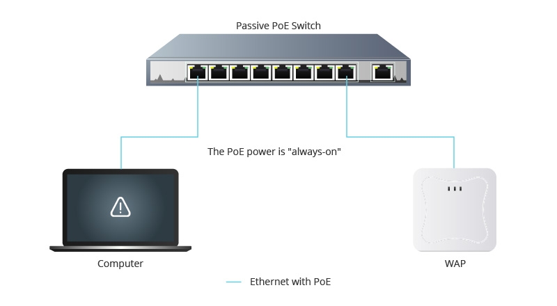
Passive PoE, also known as the passive Power over Ethernet, is a non-standard PoE. It can also deliver power over the Ethernet lines, but without the negotiation or communication process. The passive PoE switch does not adhere to any IEEE standard. The power is “always-on” when using a passive PoE switch in networks, which means it always sends electric current out over the Ethernet cable at a certain voltage regardless of whether the terminal device supports PoE or not. So using passive PoE switch may burn out the terminal devices if they’re not prepared for electrified Ethernet cables.

Active vs. Passive PoE Switch: What Are Their Differences?

As mentioned above, active PoE switches and passive PoE switches can both provide PoE connections but in very different ways. Besides that, they also differ in PoE power supply pinout, Ethernet support, cost, etc.

Active vs. Passive PoE Switch: PoE Power Supply Pinout

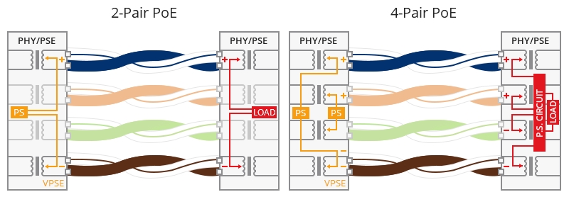
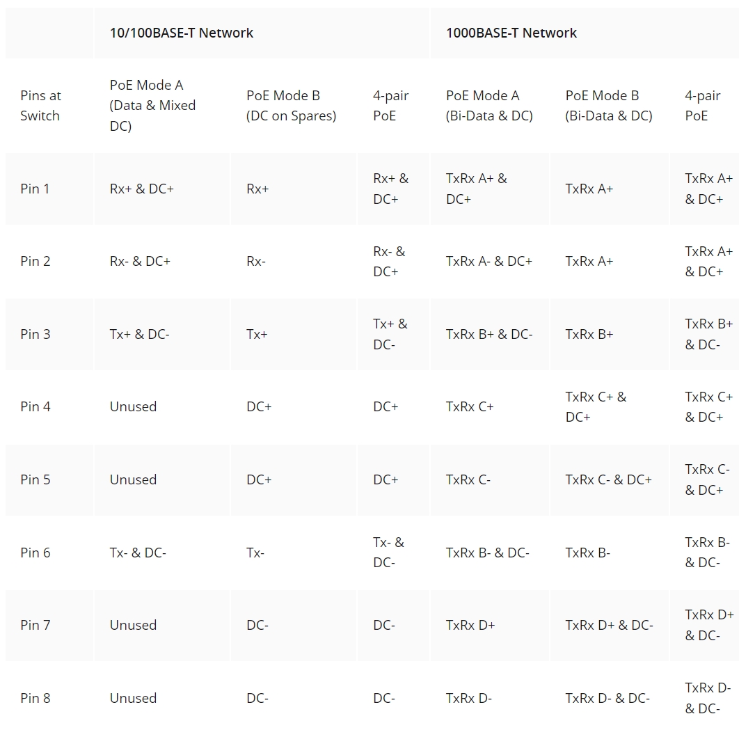
As we know, there are three methods for PoE switches to supply power: PoE Mode A, PoE Mode B and 4-pair PoE. In PoE Mode A, power is delivered simultaneously with data over pins 1, 2, 3, and 6. In PoE Mode B, power is injected onto pins 4, 5, 7, and 8. And 4-pair PoE delivers power over all 8 pins simultaneously. Active PoE switch can support all PoE Mode A, PoE Mode B and 4-pair PoE, while passive PoE switch can only support PoE Mode B. For more details about PoE Mode A, PoE Mode B and 4-pair PoE, you can check: How Does PoE Switch Deliver Power for Your Devices?

Active vs. Passive PoE Switch: Ethernet Support

Active PoE switches can support 10/100/1000Mbps Ethernet up to 100m over Cat5/5e/6 cable. Passive PoE switches, however, commonly support 10/100 Mbps Ethernet up to 100m. Thus active PoE switches can be applied in both traditional 10/100BASE-T and modern 1000BASE-T PoE networks. While passive PoE switches are usually used in the past 10BASE-T and 100BASE-T PoE networks.

Active vs. Passive PoE Switch: Cost

All active PoE switches are equipped with the built-in PoE power controller which performs the function of PD device detection and classification. While the passive PoE switch has no such component and function. Therefore it is reasonable to see the price of the active PoE switch is higher than that of the passive PoE switch.

To sum up, active and passive PoE switches mainly differ from each other in the following aspects:

 Active PoE SwitchPassive PoE Switch
StandardIEEE 802.3af/at/btN/A
Power InjectionAfter NegotiationImmediately
Power Supply ModePoE Mode A/PoE Mode B/4-Pair PoEPoE Mode B
Ethernet Support10/100/1000BASE-T10/100BASE-T
Max. Distance100m100m
SafetyHighLow
CostMediumLow

Active vs. Passive PoE Switch: Which to Choose?

From the above content, we can say that for safety concerns, active PoE switches should always be our top choice for powering up remote IP phones, IP cameras, wireless access points, and other PD devices. However, you may also consider passive PoE switches if there is a tight budget. But remember that the passive PoE switch has no power detection function. So it is important to make sure the passive PoE switch you buy matches the power specifications exactly to the PD device you are trying to power on. Otherwise, you can easily burn up your PD device. In addition, you should never connect computers and other non-PoE devices to the passive PoE switch.

Related Article:

Powering PoE Switch From A PoE Switch: Is It Possible?

PoE Switch vs. PoE Injector: Which One to Choose?

Article Source: Active vs. Passive PoE Switch: Which Should We Choose?

Understanding PoE Standards and Wattage

PoE (Power over Ethernet) technology allows PSE (Power Sourcing Equipment, such as a PoE switch) to use Ethernet cables to deliver both power and data simultaneously to PD (Powered Device, like IP cameras and VoIP phones), which can simplify cabling installation and save cost. Different PoE standards like IEEE802.3af,802.3at, and 802.3bt are released by IEEE (Institute of Electrical and Electronic Engineers) to regulate the amount of power delivered to those PDs. Then how much do you know about those PoE standards and PoE wattage? How many PDs can be connected to a PSE based on different PoE wattages? Here it offers a detailed explanation.

PoE Standards Introduction

PoE standards come in three types: IEEE 802.3af, IEEE 802.3at, and IEEE 802.3bt. These standards define the minimum power that Power Sourcing Equipment (PSE) can deliver and the maximum power that Powered Devices (PD) will expect to receive.

PoE Standards and PoE Wattage

Figure 1: IEEE 802.3af, IEEE 802.3at and IEEE 802.3bt Introduction

1. IEEE 802.3af (Standard PoE)

Operating within a voltage range of 44-57V and delivering a current of 10-350mA, IEEE 802.3af provides a maximum power output of 15.4W per port. Due to Ethernet cable power loss, the minimum guaranteed power available at the PD is 12.95W per port. This standard supports devices like VoIP phones and sensors.

2. IEEE 802.3at (PoE+)

As an updated standard, PoE+ is backward-compatible with IEEE 802.3af. It operates with a supply voltage ranging from 50V to 57V and a supply current of 10-600mA. PoE+ delivers up to 30W of power on each PSE port, ensuring a minimum power output of 25W per port. This standard is suitable for devices like wireless access points and video conferencing systems.

3. IEEE 802.3bt

IEEE 802.3bt is the latest PoE standard that defines two types of powering/wattage standards – Type 3 and Type 4. They will increase the maximum PoE power by delivering more power through two or more pairs of Ethernet cables. In Type 3 and Type 4 modes, PSEs will identify the PDs and allocate power based on the maximum power requirement of the PDs, resulting in an enhanced power delivery system. The standard will include support for 2.5GBASE-T, 5GBASE-T, and 10GBASE-T while existing standards have a maximum speed of 1-Gbps. It’s designed for demanding applications such as laptops and LED lighting.

a. Type 3 (PoE++)

Type 3, also known as PoE++, can provide up to 60W per PoE port (ensuring a minimum of 51W on each PD port). It’s suitable for powering devices such as video conferencing systems components.

b. Type 4 (Higher-Power PoE)

Type 4 offers a maximum power output of 100W per PoE port (with a minimum of 71W on each PD port). This level of power delivery is ideal for devices like laptops and TVs.

Both the two modes of IEEE 802.3bt are backward compatible with 802.3af and 802.3at. The following table concludes the specifications of the PoE standards, including PoE wattage.

NameIEEE  StandardPD Min. Power Per PortPSE Max. Power Per PortCable CategoryPower Over PairsReleased Time
PoEIEEE 802.3af12.95W15.4WCat5e2 pairs2003
PoE+IEEE 802.3at25W30WCat5e2 pairs2009
PoE++IEEE 802.3bt51W60WCat5e2 pairs class0-4, 4 pairs class5-62018
PoE++IEEE 802.3bt71W100WCat5e4 pairs class7-82018

Understanding PoE Wattage

As mentioned above, IEEE 802.3af delivers a maximum of 15.4W per port, while PoE+ supports up to 30W. The challenge arises when planning to connect multiple devices to a single PoE/PoE+ switch. It’s essential to ensure that the total power requirements of these devices do not exceed the switch’s maximum power wattage.

For example, let’s take the FS S3400-24T4FP, a managed PoE+ switch with 24 RJ45 ports and 4 SFP ports. Compliant with IEEE 802.3af/at standards, this switch has a total power budget of 370W. This means it can concurrently power 24 devices compliant with PoE standards (15.4W x 24 = 369.6, which is less than 370W). It can also support 12 devices compliant with PoE+ standards (30W x 12 = 360W, which is again less than 370W).

Figure 2: Applications of FS PoE+ switches.

But there’s no need to worry, modern network switches are intelligent. When a device is connected, they automatically detect whether it’s compatible with PoE or PoE+. If it’s a PoE-enabled device requiring 5W, the switch supplies precisely that. If the device demands 20W, the switch steps up. But if you connect a device without PoE capability, rest assured, the switch will deliver data only.

How Much PoE Wattages are Need?

The power needs of your devices depend on what you’re connecting. Most devices, such as security cameras, IP phones and standard wireless APs, require no more than 30 watts.

However, some devices, like 802.11ac wireless APs with multiple USB ports and radios, need over 30 watts for peak performance. For these cases, PoE++ or PoH switches are the solution. Keep in mind that some devices can adapt to lower power availability by using fewer radios or disabling features.

FS Network Switches: Your PoE Solution

FS now offers PoE/PoE+/PoE++ switches that adhere to the PoE standards, providing enhanced security and improved capabilities. They are available in 8/16/24/48 port options. These switches support layer 2+ switching features like VLAN. They also offer advanced management like WEB, CLI, TELNET, and SNMP. FS PoE/PoE+ switches can power any 802.3af or 802.3at device on the market, offering flexibility and security. The following table lists the specifications of 4 FS PoE/PoE+/PoE++ switches.

ModelPoE Standard PortSwitch CapacityPower BudgetForwarding RateFansAC/DC Power Supply
S3260-8T2FPIEEE 802.3af/at8x RJ45 | 2x SFP20 Gbps240W15 MppsWith FansAC
S3410-24TS-PIEEE 802.3af/at24x RJ45 | 2x SFP+, 2x RJ45/SFP128 Gbps740W96 MppsWith FansAC/DC
S5860-24XB-UIEEE 802.3af/at/bt24x Base-T | 4x SFP+, 4x SFP28760 Gbps740W565 MppsWith FansAC

Summary

Understanding PoE standards and wattage is crucial for efficient device connections. By matching your device’s power requirements with the right PoE standard, you ensure seamless operation. PoE technology simplifies complex cabling and provides flexibility in power delivery.

Related Article:

How to Avoid Overheating in PoE Cabling?

What Is PoE and Power Over Ethernet Switch?

Article Source: Understanding PoE Standards and Wattage

MDI vs MDIX And Auto MDI/MDIX Basics

MDI/MDIX are types of Ethernet interface (both physical and electrical/optical) in a computer network used to carry transmission. They must be connected using the right twisted pair cable so that the transmission pair on one end is linked to the receiving pair on the other end, and vice versa. So what exactly are MDI vs MDIX ports? How do you choose the right Ethernet cabling when connecting MDI to MDIX or MDIX to MDIX? This post will address these issues and offer some insights into auto MDI/MDIX technology.

MDI vs MDIX: What Is the Difference?

MDI (Medium dependent interface), also known as an uplink port, is an Ethernet port connection typically used on the NIC (Network Interface Card) or Integrated NIC port on a PC. The transmission signals on a NIC must go to receiving signals on the hub or network switch, so the latter devices have their transmission and receiving signals switched in a configuration known as MDIX – the “X” here represents “crossover”, indicating the reverse of input and output signals.

MDI to MDI using crossover cable

MDIX (Medium Dependent Interface Crossover) is an 8P8C port connection often found on a computer, router, hub, or network switch. Since MDIX is the crossover version of the MDI port, the pins 1 & 2 (transmitting) on an MDI device go to pins 1 & 2 (receiving) on an MDIX device via a straight through cable. Similarly, pins 3 & 6 (receiving) on an MDI device go to pins 3 & 6 (transmitting) on an MDIX device. In this case, the MDIX port eliminates the need for a crossover twisted pair cabling.

MDI to MDIX using straight through cable

MDI vs MDIX: How to Choose the Right Cabling?

In general, end stations like PCs or workstations use an MDI interface, whereas hubs and network switches use MDIX interfaces. On other network devices like routers, multiple MDIX ports and a single MDI port often co-exist. The MDI port on the router is designed to connect a cable modem. Both ports are labeled MDI or MDIX to help you choose the right type of cable. As a rule, MDI ports connect to MDIX ports via straight-through twisted pair cabling. As for MDI-to-MDI or MDIX-to-MDIX connections, crossover twisted pair cables are deployed. In some cases, network hubs or switches are built with an MDI port (often switchable) in order to connect to other hubs or switches without a crossover Ethernet cable.

What About Ethernet Auto-MDI/MDIX?

As aforementioned, an Ethernet crossover cable is adopted to connect two ports of the same configuration (i.e. MDI-to-MDI or MDIX-to-MDIX). However, it may generate some confusion and inconveniences when deploying two different kinds of Ethernet cables. The auto-MDI/MDIX technology is developed to fix this problem: It automatically switches between MDI and MDIX as required. Auto MDI/MDIX ports on newer device interfaces detect if the connection requires a crossover, then automatically choose the MDI or MDIX configuration to properly match the other end of the link. In this case, it doesn’t matter if you using straight through or crossover cables. The chart below shows cable types for MDI/MDIX and auto-MDIX.

FS.com Gigabit PoE Switch With Auto MDI/MDIX

The latest routers, hubs and switches (including some 10/100, and all 1GB or 10GB Ethernet switch) use auto MDI/MDIX to automatically switch to the proper configuration once a cable is connected. FS.com 48 port switch S1600-48T4S is one of them. This Gigabit PoE+ managed switch comes with 48×10/100/1000Base-T RJ45 Ethernet ports and 4x 10G SFP+ slots, offering up to 180Gbps switching capacity, enterprise-class features and superior network security. The built-in auto-MDI/MDIX provides fast plug-and-play setup and eliminates the need for a crossover cable. It can also detect the link speed of the attached device and makes adjustments according to the compatibility and performance requirements, enabling the switch to be backwards compatible with legacy network devices.

gigabit poe switch with auto mdimdix

Conclusion

To sum it up, MDI is an Ethernet port on end stations like PCs and workstations, whereas MDIX on hubs and network switches is the crossover version of MDI. You should employ straight through Ethernet cable for an MDI-to-MDIX connection and crossover cable for either MDI-to-MDI or MDIX-to-MDIX configuration. The auto MDI/MDIX connection address the MDI vs MDIX issues by automatically switching between MDI and MDIX, so you can opt for the cable types that suit your needs. If you still have problems regarding MDI/MDIX and auto MDI/MDIX technology, feel free to contact us at sales@fs.com.

Related Article:

8 Port PoE Switch Recommendations

What Is PoE and Power Over Ethernet Switch?

Article Source: MDI vs MDIX And Auto MDI/MDIX Basics

How to Avoid Overheating in PoE Cabling?

Power over Ethernet (PoE) technology, which combines power and data transmission together over a single cable, has made great advances over the last decades. Applications for PoE have extended from the VoIP phone and security camera to IoT devices including medical devices, access control systems for intelligent buildings, etc. Every evolution in PoE technology has witnessed the transition to higher power level, however, the overheating issue along with higher power in PoE cabling becomes an essential issue. This post will discuss the heat rise with high power PoE as well as exploring solutions to avoid overheating problems.

Evolution of PoE Standards

As the PoE market continues to grow, PoE standards go through several generations of versions from the primary IEEE 802.3af standard to the latest IEEE 802.3bt standard to accommodate the market needs. In the following chart, we will take a closer look at the four PoE standard types.

Type 1Type 2Type 3Type 4
NamePoEPoE+PoE++, UPoEHigh-Power PoE
PoE StandardIEEE 802.3afIEEE 802.3atIEEE 802.3btIEEE 802.3bt
Max. Power per Port15.4 W30 W60 W100 W
Power to PD12.95 W25.5 W51 W71.3 W
Twisted Pair Used2-Pair2-Pair4-Pair4-Pair
Supported CablesCat5eCat5eCat5eCat5e
Typical ApplicationIP phoneVideo phoneMGMT deviceLED lighting

The PoE standard IEEE 802.3af, also called PoE type 1 is an early standard designed for the low power needed devices such as traditional IP phones and the security camera. Nevertheless, with the appliance of high power devices, 12.95W is not enough for their needs, which hence becomes a limitation of PoE. Later, the early standard was followed by the IEEE 802.3at which expanded the range of PoE applications such as video telephone and dual-band desktop access, and then came the latest IEEE 802.3bt standard. Along with the increased PoE power level, it causes a temperature rise within a PoE cable. Especially when the PoE power output reaches as high as 100 W, the heat rise of PoE cable will become more obvious.

Heat Rise—The Concern Emerging With High Power PoE

In the previous IEEE 802.3af and IEEE 802.3at PoE standards, the maximum power provided by PSE is 15.4W and 30W accordingly. It is not likely to overheat at this level of power unless under extreme ambient temperatures or cable bundles are too large. Two pairs of the four pairs in an Ethernet cable is enough to carry the current. However, as the power to the end devices is increasing, PoE cabling is bound to improve to deliver higher power. The effective means to improve the cable efficiency is to increase the number of wires carrying the power—Type 3 and type 4 PoE standard uses all four pairs to inject power rather than 2 pairs used in the early standards.

Figure 1: 2-pair PoE vs 4-pair PoE

The 4-pair PoE doubled the amount of available power, enabling PoE expanding to support higher-powered devices instead of being limited to the devices needing low power such as 15W or 30W. However, high power is not the only thing requiring attention in PoE cabling. Heat rise is another one. Manufacturers and technical consortiums have worked to evaluate the thermal impact of delivering 100 Watts of power over 4-pair PoE. Apparently the increasing power increases current flow, which significantly results in an increase in cable heating.

Why Is Heat Rise a Key Issue?

Why do we consider heat rise in PoE cabling so seriously? It is all because of the negative effects of heat rise on the link stability, and cabling lifespan.

Overheat in PoE cabling can result in an increase in insertion loss. To maintain the signal quality, administrators have to shorten the cable length to compensate for the loss in the link. Heat rise will lead to the premature aging of jacketing materials. If operated under the high-temperature circumstances for a long time, the outer jacket may get broken and impact the inner construction, breaking the balance of the twisted pair cable and causing the decline of electric performance. Furthermore, since the influence of heat rise in high power PoE is irresistible, careful evaluation before the PoE cabling deployment is required in the event of subsequent disposal. Better cabling cool will help to reap the benefit of excellent transmission performance.

Common Types of High Power PoE Applications

As has been mentioned in the front section, heat rise occurs with high power PoE cabling. Driven by the need for higher power all around the world, new PoE technology is expected to progress to enable new PoE markets and widen PoE’s scope to the existing markets requiring high power. Applications that take advantage of high power PoE technology include:

  • Intelligent buildings with enterprise IoT (connected LED lighting)
  • Safe cities (high definition pan-tilt-zoom security cameras)
  • Retail POS systems and digital signage
  • High-performance wireless access points
  • Kiosks
  • Small cells

Precautions to Minimize Heat Rise in PoE Cabling

Ultimately, the overheating problem can be attributed to the cable/conductor construction and specific installation situations. The following suggestion to minimize heat rise in PoE cabling will be listed from these aspects in an exhaustive way.

1. Use higher category cabling

In general, the higher the cable category is, the lower the heat will rise. According to the testing results from Leviton engineers, the higher category cabling correlated with lower amounts of temperatures after they tested several different category types of fiber cables. For new PoE installations, TIA suggests Cat6A for use.

Figure 2: Current per category cable

2. Select cabling with a larger conductor (i.e., lower gauge number)

Heat rise can be the result of the conductor resistance in PoE applications. The larger the conductor is, the more it can reduce conductor resistance, the easier current flow it will allow for and the less heat it will generate.

3. Cable connectors should feature a solid metal body

Consider using connectors with an all-metal-body construction, instead of plastic. Compared with thermoplastic jacketing materials, mental has a higher conductivity and does better in heat dissipation.

4. Choose cables with smaller bundle size

By measuring the temperature of a large cable bundle and the smaller bundles separated from the big one, TIA identified that the core of the large cable bundle experienced higher temperature in comparison to smaller bundles. TSB-184-A developed by the TIA subcommittee recommended leaving cables unbundled to facilitate better heat dissipation. If not possible, smaller bundle sizes are recommended.

5. Install shielded cabling

It has been affirmed that the existence of a metallic shield or foil helps dissipate heat. If the cable utilizes a foil shield around each pair, it will deliver better heat-dissipating qualities than the unshielded twisted pair cables. Therefore, S/FTP or F/UTP cables are more applicable than UTP cabling systems in PoE applications.

Figure 3: Cable heat dissipation effect UTP vs F/UTP

6. Plan your PoE cable management

Group your cables as loosely as possible instead of bundling all of them as a whole. Distribute your cable or cable bundles as dispersed as possible in an available area. High cable density will contribute to more heat within the cable or cable bundles. You are suggested to use cable management tools that allow for better airflow around cables and cable bundles.

Related Articles

How to Lower Cabling Temperature for PoE?

Powering PoE Switch From A PoE Switch: Is It Possible?

Article Source: How to Avoid Overheating in PoE Cabling?

Long Range Outdoor AP Delivers Stable Outdoor WiFi

Long Range Outdoor AP plays a crucial role in maintaining a reliable WiFi connection. While indoor WiFi networks have become commonplace, ensuring a stable outdoor WiFi connection presents unique challenges. This is where outdoor WiFi access points (APs) come into play. In this article, we will delve into the concept of outdoor WiFi APs and how they can assist you in upholding a stable, high-speed internet connection beyond the reach of your regular networks.

Why Do You Need a Long Range Outdoor AP?

The importance of outdoor WiFi connections cannot be overstated, particularly in business environments. Homeowners and business owners alike rely on Long Range Outdoor APs to expand their network coverage to open spaces. For homeowners, this means enjoying seamless connectivity in gardens and patios. Business owners, especially those in the food and beverage industry like cafes and restaurants, depend on outdoor WiFi to offer dependable internet access to patrons. This service enhances customer experience by allowing guests to peruse menus, check emails, and engage on social media. Positive customer experiences, in turn, translate into favorable reviews and repeat visits, making outdoor WiFi an indispensable asset for establishments looking to thrive in today’s competitive market.

What is the Long Range Outdoor AP?

The Long Range Outdoor AP, or Access Point, is a specialized wireless device crafted for extending your network’s coverage beyond conventional indoor boundaries. Unlike typical home routers, which primarily serve indoor areas, these outdoor APs excel at delivering WiFi signals across vast outdoor spaces, making them the perfect choice for homeowners and businesses seeking dependable outdoor internet access. Long Range Outdoor APs typically feature robust, weatherproof enclosures to withstand the elements, while supporting high-speed WiFi standards for fast and reliable connections. They come in various designs and sizes to cater to different needs, including smaller units for residential use and more robust, high-capacity models for commercial and industrial applications.

Factors Impacting Long Range Outdoor AP WiFi Signals

Physical Obstacles

Physical obstacles, such as buildings, trees, and other structures, can significantly impact outdoor WiFi signals. Understanding how these obstacles affect signal propagation is essential for planning the installation of your outdoor WiFi APs. In some cases, you may need to adjust the positioning of your APs to avoid signal interference.

Weather Conditions

Weather conditions can have a substantial impact on outdoor WiFi connections. Rain, snow, and fog can reduce signal strength and reliability. Extreme temperatures, especially in very hot or cold climates, can also affect the performance of outdoor WiFi APs. When installing these devices, it’s essential to choose equipment designed to withstand the specific weather conditions in your area.

Frequency Band Selection

The choice of WiFi frequency bands, such as 2.4GHz and 5GHz, can significantly impact signal quality. In general, the 2.4GHz band offers better range but may be more susceptible to interference, while the 5GHz band provides faster speeds but has a shorter range. Selecting the appropriate frequency band depends on your specific needs and the environment in which the outdoor WiFi AP will be installed. Many APs on the market provide 2.4G frequency, such as FS AP-T567 and AP-T565. They are both Outdoor Access Points, and they can achieve seamless roaming and cloud managed to ensure business continuity.

Security Measures

Security is a critical aspect of outdoor WiFi connections. Implementing strong encryption, such as WPA3, is essential to protect your network from unauthorized access. Additionally, setting up a guest network with restricted access can enhance security, ensuring that guests can access the internet without compromising your primary network’s security.

Proper Installation of Long Range Outdoor AP

Selecting the correct installation site for your Long Range Outdoor AP is crucial. Take into account the following key factors:

Power Supply: It is essential to guarantee that your Long Range Outdoor AP receives a consistent power supply. This may involve the use of waterproof cables and appropriate power adapters to ensure uninterrupted operation.

Elevation: Position the AP at an optimal height to optimize signal coverage while avoiding potential obstructions that might degrade the signal quality.

Weatherproofing: Deploy weatherproof enclosures or protective covers to shield the Long Range Outdoor AP from the impact of adverse weather conditions, ensuring its longevity and performance reliability.

After installation, configure the outdoor AP to meet your network requirements. Test the connection to ensure everything is operating correctly and that the device provides the necessary signal coverage. Additionally, it is essential to conduct regular checks on the device’s performance, clearing any dust or dirt, to ensure stability.

Conclusion

Long Range Outdoor AP provides a practical solution to extend your network coverage and ensure a seamless internet connection, whether you’re at home, in a commercial outdoor space, or hosting an event. By understanding the benefits of outdoor WiFi APs, knowing how to choose the right device, and following best practices for installation and maintenance, you can enjoy uninterrupted connectivity in your outdoor spaces, no matter the weather or location. Don’t let the great outdoors limit your online experience – invest in outdoor WiFi APs and stay connected wherever you go.

Related Articles

What is the Difference Between Wi-Fi 6 and Wi-Fi 6E?